Isolation Joint Testing with an RF – IT
Testing instructions for Dairyland products are often requested by customers wanting to verify decoupler operation. For a simple yet effective method of testing all Dairyland products, refer to: Dairyland Product Testing – Indirect Test
When isolation testing is required at an isolation joint that has a decoupler mounted on it, additional considerations need to be taken to confirm isolation when using an isolation checker also known as an RF-IT.

Dairyland SSD on an isolation flange
How does an RF-IT work?
AN RF-IT uses a radio frequency to determine continuity on the substrate being tested. The frequency is sent out from Probe A and if Probe B does not receive the signal, electrical isolation is confirmed. If the frequency is received by Probe B, electrical isolation is not confirmed
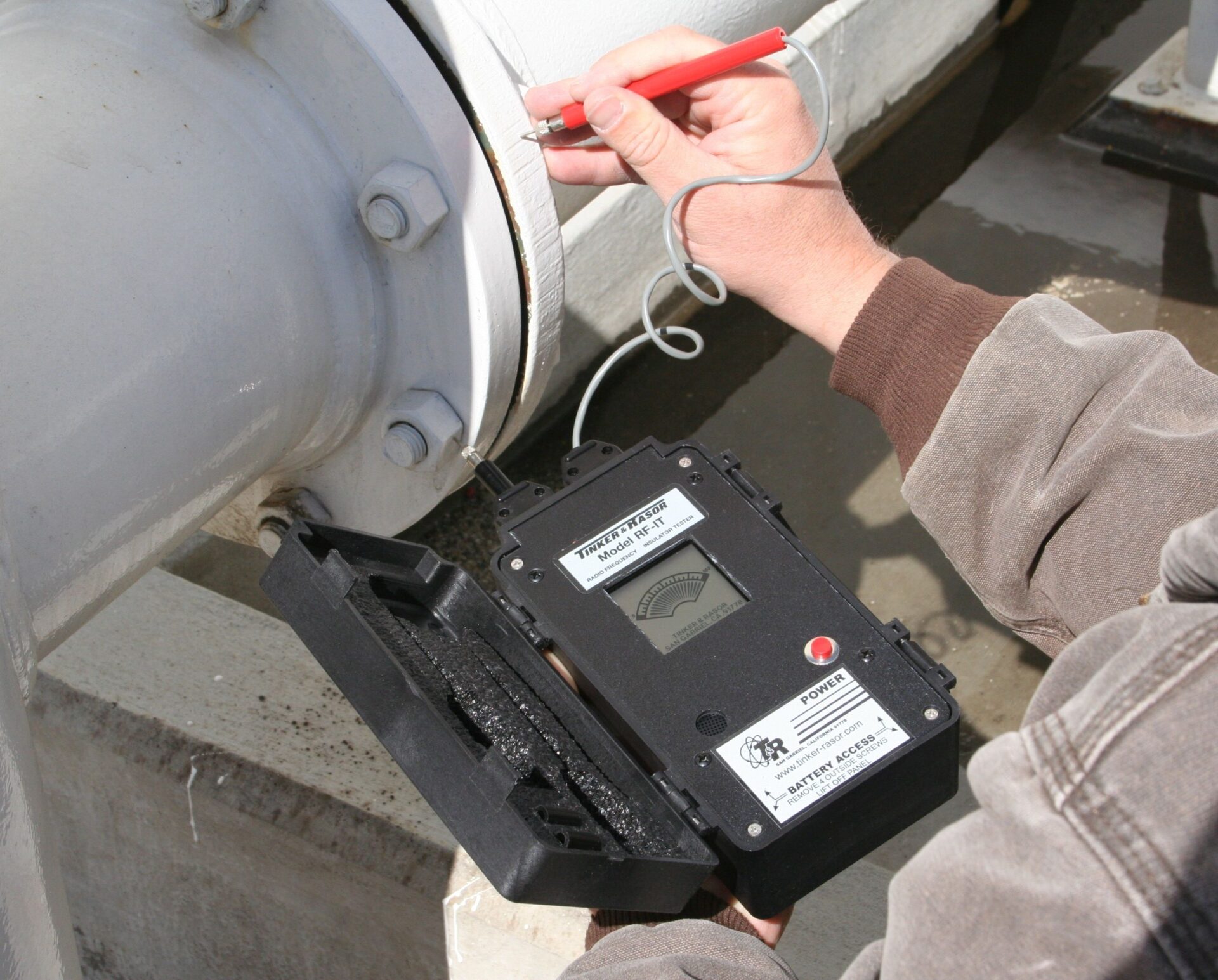
Photo courtesy of Tinker & Rasor
To confirm electrical isolation at an isolation joint using an RF-IT, a technician digs the tip of Probe A through the coating on one side of a flange and the tip of Probe B on the other side of the flange. If there is electrical isolation, the display on the device will not change and there will be no tone or beeps emanating from it. If there is continuity, the display on the RF-IT will change and there will be a series of beeps or a continuous tone, depending on the level of continuity between the two sides. The technician will then test each bolt head by digging Probe A into the side of the flange connect Probe B to each bolt head on the opposite flange to find the short(s) that need repair. Once one side of the flange is completed, the technician will repeat these steps to test each bolt head on the other side of the flange. Typically, the shorted path is located at a bolt and the technician will need to rework or replace the bolt isolation sleeve to correct this.
How does an RF-IT work with a Decoupler?
A Dairyland decoupler has a very low impedance to AC by design, this is what allows it to be installed in the recommended applications as an effective ground fault path and as a path for induced AC to go to ground. Since a decoupler is AC continuous, this means that the frequency used in a RF-IT also passes right through a decoupler. Therefore, a decoupler appears shorted to an RF-IT giving the false impression that either the flange is not isolated or that the decoupler has failed and is no longer providing DC isolation. Information about this can also be found on RF-IT manufacturer’s websites.
Additional Testing Procedures for an Isolation Flange with a Decoupler
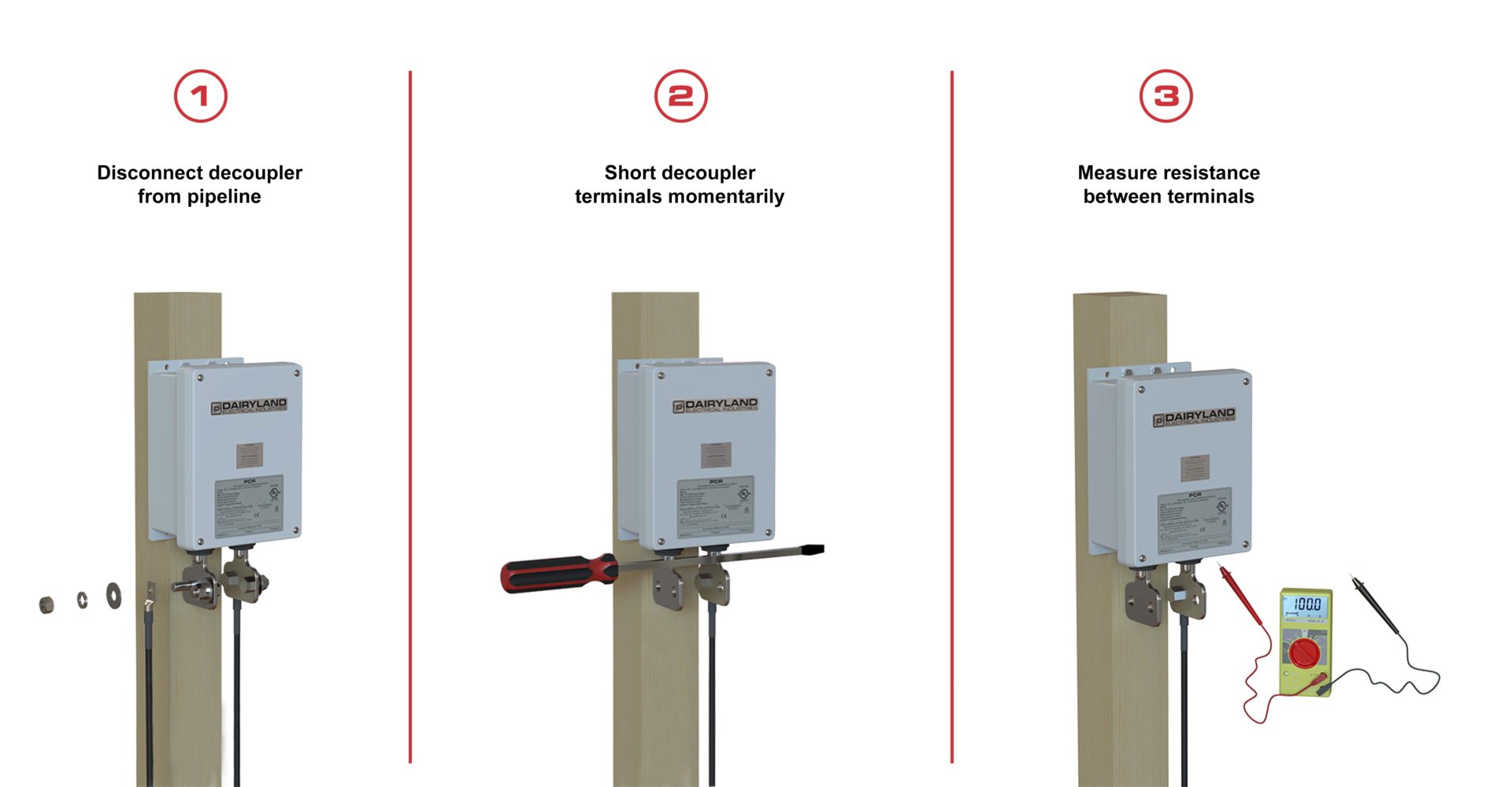
Test each product separately from the other.
In order to perform a separate test on the isolation flange, temporarily disconnect the decoupler from the isolation flange following company practices and safety procedures. Once the decoupler has been safely disconnected, test the isolation flange as per the RF-IT’s Manufacturer’s instructions. Note that only one side of the decoupler needs to be removed for this test.
Then perform a direct test on the decoupler to determine that the decoupler is operating correctly by following the decoupler direct testing procedure found here: Decoupler Testing – Direct Test – Dairyland Electrical Industries
After testing both products and determining the isolation joint has proper electrical isolation and the decoupler is functioning properly, reconnect the decoupler to the isolation flange and document your findings. Should you have questions at any time during this process, please contact our technical support team for further assistance.
Want To Dive Deeper?
Join One of Our Learning Events.
Our event schedule provides you the in-depth product and application training you need to correctly apply Dairyland products.