Technical Article
Determining AC Fault Current
An AC fault results in the heavy flow of alternating current available from an electrical source during abnormal conditions. This current can be induced onto a structure without any metallic connection to it, such as in the case of pipelines in a common corridor with power lines. Current can also flow via conduction in grounding conductors, the soil, or other unintended paths back to the source, affecting cathodically protected structures.
Different applications involve varying levels of AC fault current, but in all cases some value of phase-to-ground AC fault current must be determined, even if only estimated. Some applications may not have notable AC fault current exposure, and the lowest standard product fault rating may be chosen. Applications are listed below, with suggested methods of determining the AC fault current for each.
AC Fault Current by Application
For a discussion of AC fault current data, choose your site description or application:
• Insulated Joint Protection
• AC Voltage Mitigation on Pipelines
• Decoupling Electrical Equipment (e.g. motor-operated valve)
• Decoupling Power Company Ground from User Site/Station Ground at the Transformer
• Decoupling Power Company Ground from User Site/Station Ground at User Panel
• Stray Voltage Mitigation at Farms (Primary-to-Secondary Isolation)
• Lead-Sheath or Pipe-Type Power Cable Decoupling from Substation Ground
• Blocking GIC/Transformer Neutral Decoupling
Contact Dairyland for assistance with any aspect of AC fault determination.
Exposure level: Since insulated joints are not usually directly tied via metallic connection to an AC faulting source, the fault currents are usually low to moderate. Higher exposure exists for insulated joints on pipelines serving power plants, or where the pipeline may become the metallic return path for fault current to the source.
Calculation method:
A) For insulated joints in a common corridor with power lines, where an AC mitigation study is being performed, the mitigation consultant can advise the expected or modeled fault current level.
B) For common corridor sites with no calculations or data available, typical values obtained by Dairyland from mitigation consultants in the past have indicated that a reasonable decoupler value would be 3.7kA. For cases where high fault currents are expected due to close proximity or other factors, select a higher product rating as appropriate.
C) For sites not in a common corridor with power lines, and not in metallic contact with AC fault sources, Dairyland product ratings lower than 3.7kA may be chosen.
AC Voltage Mitigation on Pipelines
Exposure level: Unless the pipeline has a direct, metallic connection to a power line grounding system (which is not recommended), the fault current is kept to moderate levels under most conditions due to the resistance offered by the pipeline coating and soil, and the limitations of the inductive coupling effect that produces this voltage. Direct metallic bonding of the pipeline to the transmission tower will greatly increase the exposure of the pipeline and coatings to fault current and lightning, and is not recommended.
Calculation method:
A) Manual calculations, or more commonly software analysis, are used to determine the fault current magnitude that can be picked up by a pipeline system. Specialized mitigation consultants can assist in performing this analysis.
B) An alternate method for estimation is to use a percentage of the power company’s maximum phase-to-ground fault current magnitude and time duration. This assumes that such data can be obtained from the power company, and is usually most useful if their fault current is relatively low, indicating that a modest decoupler rating may be acceptable. Higher fault values could indicate that an unnecessarily high decoupler rating is needed. From typical data obtained from mitigation consultants, a common range of fault values used from numerous past projects is from 3.7kA to 10kA.
Decoupling Electrical Equipment (e.g. motor-operated valves)
Also for: Ship-to-Shore Galvanic Isolation
Exposure level: The grounding conductor of an AC voltage system is designed to carry the full phase-to-ground fault current in the event of a fault (e.g. shorted conductors or motor winding failures). Placed in this grounding conductor, the Dairyland device would be exposed to the entire available fault current, and should be rated for such. Dairyland PCR, PCRH, PCRX, SSD, OVP, OVP2 and Marine Galvanic Isolator devices are all certified to US and Canadian standards for use in grounding conductors for electrical equipment.
Calculation method: The full available fault current in the AC circuit in question should be used. The methods for sizing include (in order of preference): A) comparison of the grounding conductor size to fault withstand graphs for cables, B) using the fuse or breaker clearing curve for the circuit in question, or C) calculation of the fault current at the transformer (worst case).
Each method is described below.
A) Comparison of the grounding conductor size to fault withstand graphs for cables
Device ratings can be indirectly estimated by comparison to the AC fault capability of the conductor used on the circuit of interest. This is based on the assumption that the conductor was originally sized correctly for the available fault current, and will generally result in a conservative selection. Locate the conductor size used on your circuit, then compare the current/time values in the withstand graph to the Dairyland device as shown in the figure below, choosing a product rating that approximates or exceeds the conductor rating.
![]()
Available Short-Circuit Currents for Insulated Copper Conductors (Ref NACE SP0177)
As this is an indirect method of fault sizing, it may be appropriate in some cases to have a Dairyland product rated below the conductor withstand value, if other factors, such as total conductor length, indicate that the fault current is substantially lower than the maximum conductor withstand. The following table summarizes the most common fault values and corresponding wire sizes.
| Wire Size (AWG) | Dairyland Product Fault Rating |
| #6 and smaller | 3.7kA |
| #4 | 5kA |
| #2 | 10kA |
| Larger than #2 | Contact Dairyland |
B) Comparison to fuse/breaker clearing curves
The next clearing device, such as a fuse or breaker, upstream (toward the source) of the circuit of interest can be compared to the Dairyland device ratings. The fuse or breaker “total clearing time” curve should be used, and a Dairyland device rating should be chosen to exceed these curve values. On a clearing curve graph, the Dairyland device ratings should appear to the right of the fuse/breaker clearing curve as shown in the example below.
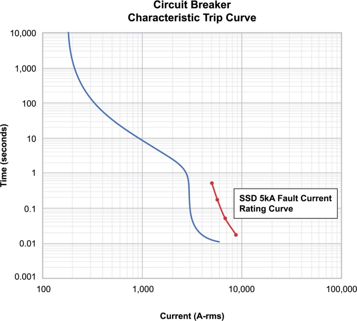
Example Circuit Breaker Trip Curve Compared to Decoupler AC Fault Current Rating
In the case of a ship where upstream breaker data is not known, the main shore power breaker on the ship could be used to obtain an estimate of the AC fault current.
C) Calculations based on the source fault current at the transformer
Unless the user has fault data for the exact circuit of interest, a conservative estimate can be achieved by starting with the fault current at the site transformer. If desired, further refinement can be done by calculating current reductions due to conductor impedance. This method is most useful for smaller electrical facilities; use at larger facilities may provide overly conservative values.
The maximum fault current available at the transformer terminals is determined by the following formula, using data from the transformer nameplate, which can be supplied by the power company or a site engineer.
Secondary full load current = Single Phase Transformer kVA / (Secondary kV)
OR
Secondary full load current = Three phase transformer kVA / (Secondary kV)(√3)
Then
Secondary fault current = Secondary full load current x 100 / Percent transformer impedance
This is the maximum fault current at the transformer, which will be reduced by conductor impedance. This reduction can be estimated using wire characteristics for various cross-sections and lengths.
Decoupling Power Company Ground from User Site/Station Ground at Transformer
Exposure level: A Dairyland device connected as the sole bond between a power company grounded neutral system and the secondary grounded neutral system at a station or other site with cathodic protection will be exposed to, and should be rated for, the full primary fault current from the power company distribution system.
Calculation method: The primary phase-to-ground fault current (magnitude and duration) at the transformer should be requested from the power company’s distribution engineering department. If this is not available, the fuse clearing curve can be requested from the utility. A Dairyland product rating should be chosen that exceeds the “total clearing time” of the fuse or breaker. A graph of current versus time values should result in the Dairyland device to the right of the clearing device curve.
Decoupling Power Company Ground from User Site/Station Ground at User Panel
Exposure level: A Dairyland device connected as the sole bond between a power company grounded neutral system and the secondary grounded neutral system at a station or other site with cathodic protection will be exposed to, and should be rated for, the full secondary fault current from the power company transformer.
Calculation method: Unless the user has fault data given to them by others, the secondary fault current available at the terminals of the transformer should be determined. This can be calculated from the transformer nameplate data. If desired, further refinement can be done by calculating current reductions due to conductor impedance, for the distance between the transformer and the decoupler at the panel.
The maximum fault current available at the transformer terminals is determined by the following formula, using data from the transformer nameplate, which can be supplied by the power company or a site engineer.
Secondary full load current = Single Phase Transformer kVA / (Secondary kV)
OR
Secondary full load current = Three phase transformer kVA / (Secondary kV)(√3)
Then
Secondary fault current = Secondary full load current x 100 / Percent transformer impedance
This is the maximum fault current at the transformer, which will be reduced by conductor impedance. This reduction can be estimated using wire characteristics for various cross-sections and lengths.
Stray Voltage Mitigation at Farms (Primary-to-Secondary Isolation)
Exposure level: A Dairyland device connected as the sole bond between a power company grounded neutral system and the secondary grounded neutral system at a farm or residence will be exposed to, and should be rated for, the full primary fault current from the power company distribution system.
Calculation method: The primary phase-to-ground fault current (magnitude and duration) at the transformer should be determined by the power company’s distribution engineering department. If this is not available, the transformer fuse clearing curve can be examined. A Dairyland product rating should be chosen that exceeds the “total clearing time” of the fuse or breaker. A graph of current versus time values should result in the Dairyland device to the right of the clearing device curve.
Lead-Sheath or Pipe-Type Power Cable Decoupling from Substation Ground
Exposure level: A Dairyland decoupler is typically used at each end of a power cable circuit, between the sheath/pipe and substation grounding system. As the sole grounding path, the Dairyland device may see the full phase-to-ground fault current on the transmission system, and should be rated for this value.
Calculation method: As this would likely apply only to transmission cable systems owned by power companies, the power company can turn to their transmission engineering department for the phase-to-ground fault current magnitude and duration. These values have already been modeled for the transmission system, and are readily available. Choose a Dairyland device AC fault rating that exceeds the modeled system fault current and time duration. Dairyland publishes 1, 3, 10, and 30 cycle current values to assist with product selection. Interpolation between published values can be done – contact Dairyland for additional guidance.
Blocking GIC/Transformer Neutral Decoupling
Exposure level: The grounded transformer neutral that is affected by GIC (Geomagnetic Induced Current) or DC currents can have a Dairyland decoupler placed in series in the bond/neutral. This subjects the decoupler to the full fault current available in the neutral.
Calculation method: The full available fault current should be used, which can be obtained from the power company substation or transmission engineering department for the neutral (phase-to-ground) fault current magnitude and duration. These values should be readily available. Choose a Dairyland device AC fault rating that exceeds the modeled system fault current.
Want To Dive Deeper?
Join One of Our Learning Events.
Our event schedule provides you the in-depth product and application training you need to correctly apply Dairyland products.