The Role of DC Decouplers with Cathodic Protection Systems
Cathodic Protection (CP), when properly applied, is an effective technique to minimize the natural corrosion process that occurs on pipelines, tanks and other buried steel structures. To maintain effective CP coverage with minimal current demand, the structure must be well-isolated from earth for DC current flow. This is commonly accomplished using high resistance coatings, isolation joints, dielectric fittings and isolation pads.
However, these structures require electrical earthing for both personnel safety and protection of the structure from damage due to over-voltage conditions. Earthing bonds for AC mitigation systems, AC fault and lightning protection and electrical equipment protection all introduce undesired paths for CP current to return to the rectifier by way of the structure. This requires the CP system to protect significantly more material surface area for which it was not designed. As a result, it is often difficult to maintain adequate CP potentials on the structure that is to be protected.
DC decouplers have a long history of providing effective DC isolation of cathodically protected structures from other objects and earthing systems while simultaneously bonding the structure to earth for AC and lightning. However, decoupling devices are often misapplied or not applied at all due to simple misunderstanding of how CP current flows through earthing systems.
THE CHALLENGES WITH EARTHING SYSTEMS
CP systems, and external corrosion protection in general, require that the structure be electrically well-isolated from earth. Since CP systems are designed to protect only relatively small defects in the coating of the protected structure, the degree of isolation determines the efficiency and effectiveness of the CP system in protecting the structure. Certainly, the less surface area of the structure that is directly in contact with earth, the less CP current is required for protection. This is the basic function of high resistance pipeline coatings. Additionally, every surface on the structure that interfaces other earthed structures must be insulated to minimize CP current flow through the other structures. This is accomplished using isolation kits and monolithic joints at piping connections, dielectric fittings for smaller piping connections, conduit and sensor connections and isolation pads for above-ground pipe supports.
In addition to these mechanical interfaces, there are electrical connections between structure and earth for which continuity must be maintained to protect the structure and personnel from potential over-voltage conditions. These connections include earthing bonds for AC mitigation systems and protection from AC faults and lightning and earthing bonds for electrical equipment.
AC Mitigation Earthing Paths
The main intent of AC mitigation systems is to dissipate unwanted voltage along the pipeline resulting from induced AC from nearby power transmission lines and AC faults and lightning. The general technique for mitigating induced AC pipeline voltage is to connect the pipeline at appropriate locations to a suitably low impedance earthing system in order to collapse the voltage to a safe value. The earthing system is commonly bare zinc ribbon or copper wire run in parallel with the pipeline.
The design process typically begins with software modeling by specialized consultants, inputting various factors such as soil resistivity, separation distance and voltage to arrive at a voltage map at all points along the pipeline. Then, by applying low impedance earthing points at various locations along the affected area, the AC effects under steady-state and fault conditions can be modeled, and the earthing system design can be optimized to address worker safety and AC corrosion issues. Depending on many variables such as the separation distance and geometry between the pipeline and power lines, power levels, soil resistivity, pipeline coating, etc., spacing of earthing connections may vary between a few hundred meters to several kilometers.
These bonds between the pipeline and the earthing system provide additional low impedance paths for CP current to flow between the anode bed and the rectifier negative terminal and so introduce significant additional material surface area for the CP system to protect as illustrated in Figure 1. As a result, the rectifier often cannot support the increased current load and CP potentials can become compromised, leaving the structure inadequately protected.
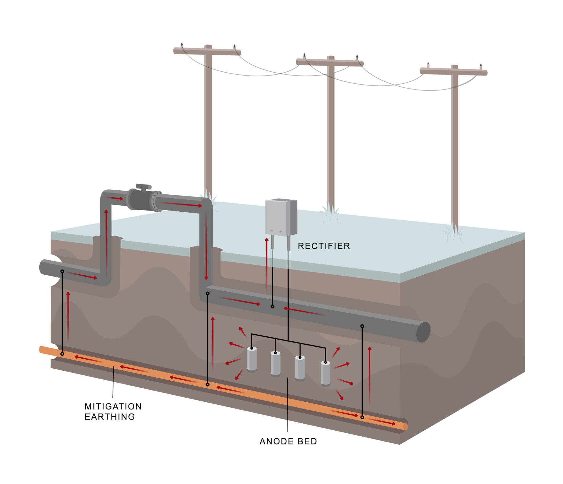
Figure 1: CP Protection of AC Mitigation Systems without DC Isolation
Electrical Equipment Earthing
It is common for electrical equipment, such as motor operated valves, to be inadvertently electrically bonded to pipelines. Consequently, the equipment, its earthing system and everything to which it is bonded, including the utility earthing system, is bonded to the pipeline. These earthing systems then become additional paths for CP current to return to the rectifier negative terminal and so present additional material to be protected by the CP system as shown in Figure 2. This can have a dramatic negative impact on CP system performance.
Electrical earthing conductors are needed to conduct AC fault current and prevent over-voltage conditions and must be left in place. National electrical codes require equipment earthing conductors to be 1) permanent and continuous, 2) rated to handle the anticipated AC fault current from the source, and 3) of low impedance to allow AC fault current to flow, permitting a clearing device (circuit breaker or fuse) to clear the fault. These define what is an “effective ground-fault current path” for safety, per the electrical codes[1]. To remove the offending conductor for convenience on the CP system is to allow an unacceptable shock hazard at the site during any over-voltage condition.
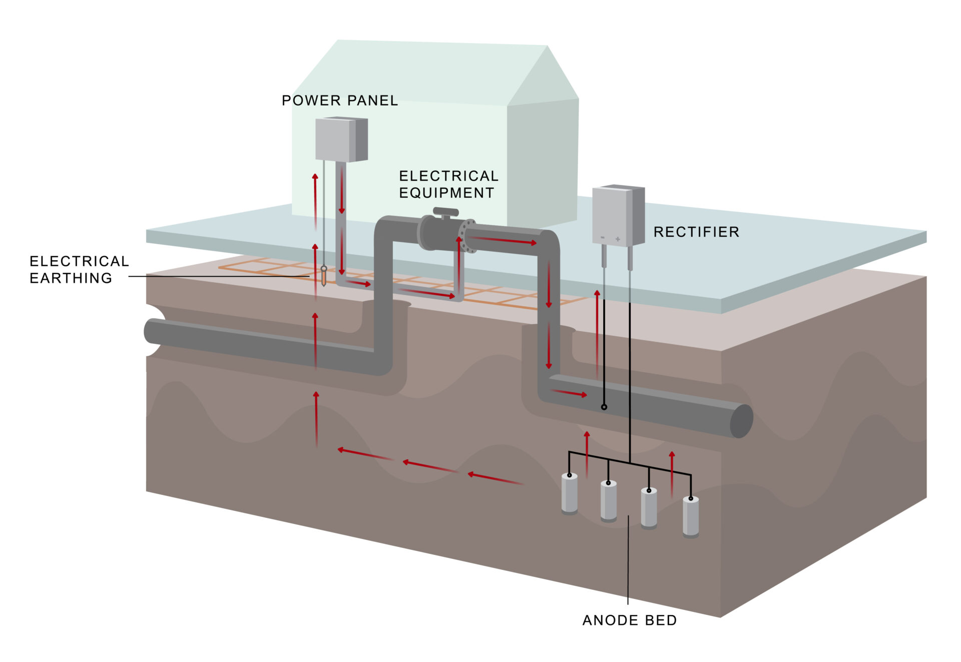
Figure 2: CP Protection of Electrical Equipment Earthing without DC Isolation
Instrumentation Earthing and Measurement Tubing
Transmitters on pipelines and tanks typically have a continuous metallic shield that covers the signal cables and may have an additional internal earthing conductor as well, as shown in Figure 3. Except in the case of a transmitter that has an electrically isolated body, the shield and earthing conductor will short the structure to the instrument earth and cause CP current to protect the instrument earthing system.
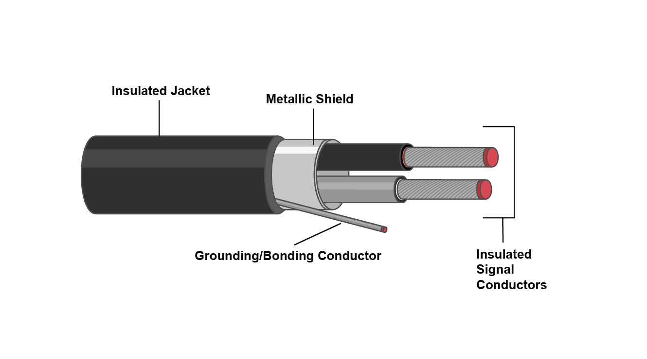
Figure 3. Typical Signal Cable
Similarly, pipeline pressure measurement or equipment control tubing often bridges between cathodically protected and unprotected structures and can introduce a path to earth for CP current.
DC ISOLATION TECHNIQUES
When faced with insufficient CP potentials due to such required earthing bonds, CP designers might be inclined to add more rectifiers and anode beds and tolerate high CP current demand. However, this is likely a prohibitively expensive option and may ultimately not provide sufficient protection.
A practical and widely accepted solution is to install DC decoupling devices in series with the bonding connections between the cathodically-protected structure and the earthing systems as shown in Figure 4. When used in series with electrical equipment earthing systems, note that the device must be specifically approved for such use and that use of DC decouplers in earthing systems must comply with local national guidelines and codes. This prevents CP current from passing through the earthing systems and so minimizes the amount of CP current required to protect the pipeline.
Solid-State Decouplers
Solid-state over-voltage protectors use high power solid-state electronic switching components to create a switch between the two structures to be isolated. Under normal conditions, this switch remains open, maintaining DC isolation between the structures. When the differential voltage across the terminals exceeds a prescribed voltage threshold, which would occur during a fault or lightning event, the switch closes virtually instantaneously, collapsing the voltage across the terminals and electrically bonding the structures. Immediately following the over-voltage event, the device then automatically switches back into the OFF state to maintain DC isolation.
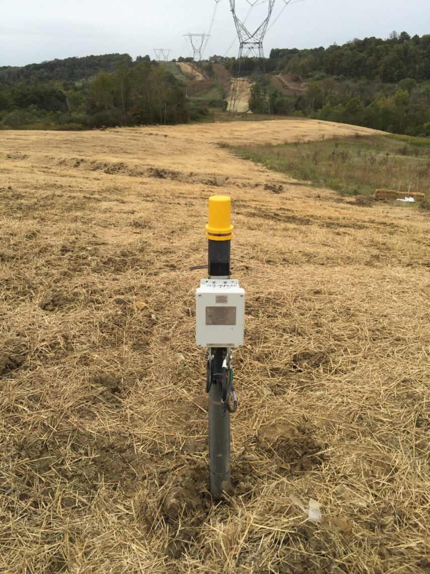
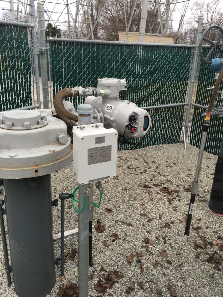
Solid-state decouplers, in addition to bonding structures during AC faults and lightning, provide a continuous conduction path for steady state AC to pass through the device at all times. By shorting steady state induced AC current, a solid-state decoupler reduces AC voltage on the pipeline and prevents the AC voltage from triggering the solid-state switch. An example of a solid state decoupler installed as part of an AC mitigation system is shown in Figure 5. In Figure 6, a decoupler is shown installed to DC isolate a motor-operated valve from electrical earthing.
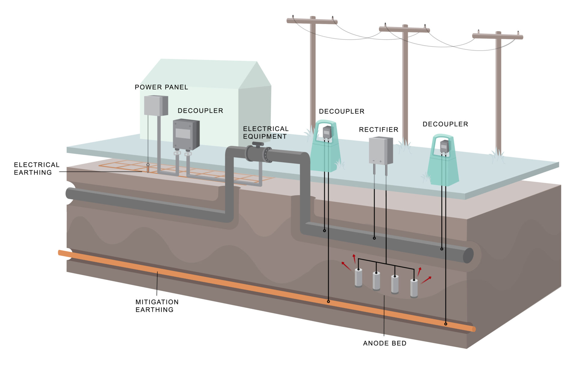
Figure 4: CP Protection with DC Isolation using Decouplers
 |
 |
|
Figure 5. Solid-state decoupler installed as a part of an AC mitigation system. |
Figure 6. A decoupler installed to DC isolate an MOV from earth. |
Polarization Cells
The polarization cell is an electrochemical switch comprised of pairs of stainless steel or nickel plates immersed in a solution of potassium hydroxide. It responds to low voltage DC current by polarizing the plates and reducing the flow of DC current. It passes higher voltage DC, steady state AC, AC faults and lightning current.
Since the introduction of solid-state devices in the 1980’s, polarization cells have become much less common due to their need for regular maintenance of fluid levels, large package size, and the fact that when they fail, they create an open circuit, which creates a potential safety hazard.
Other DC Isolation Devices
Though not considered decouplers, spark gap devices are commonly used to protect isolation joints from damage due to lightning. When the voltage across the terminals reaches a designated level, an arc bridges the product’s two electrodes and passes current. Typically, spark gaps require several hundred volts for AC and over 1000 V for lightning for the device to go into conduction. Although they do provide DC isolation, they cannot pass low voltage AC current and so are not appropriate for use with AC mitigation systems. In addition, spark gaps do not provide an effective ground fault protective path as defined by electrical codes and so cannot be used in the earthing circuit for electrical equipment.
APPLICATION REQUIREMENTS FOR DC DECOUPLERS
Decoupling products must be selected with careful examination of their electrical characteristics relative to the intended purpose in order to assure proper application.
Low Impedance for AC Faults and Lightning
One of the most basic requirements of decoupling devices is to provide a low impedance path for AC faults and lightning. During such an event, the voltage across a solid-state device clamps at the threshold voltage, which is typically 3 volts or less. Under the most extreme AC fault conditions, the maximum voltage across the terminals is less than 10V. Under lightning surge events, this maximum voltage is approximately 100V. This assures that over-voltages will be clamped to low levels during faults or lightning events, providing a significant advantage for personnel safety and for applications such as isolated joint protection.
Sufficient Device Ratings
The typical AC fault rating for pipeline applications near HVAC towers is 5kA and levels up to 15kA are not uncommon. Most solid-state devices have the ability and ratings to handle AC fault current at these levels.
Low Impedance for Steady State AC
To be effective for use as part of AC mitigation systems, decoupling devices must be able to continuously conduct steady state induced AC. This includes devices used across isolation joints if earthing points on the opposite sides of the joint are part of the same AC mitigation system. Solid-State decouplers and polarization cells both continuously conduct steady state AC. Most solid-state decouplers introduce only a few milliohms of impedance and so do not significantly affect the pipeline voltage.
Low Maintenance
Given the remote location of many pipelines, low maintenance and reliability of decoupling devices is extremely important. Since polarization cells require regular inspection to maintain liquid levels, these devices have become much less popular over recent decades.
Low DC Leakage Current
To maintain the efficiency of CP systems, it is important to minimize DC current leakage to earth through decoupling devices. Since many modern pipeline coatings provide such effective isolation, CP rectifier currents are often so low that several milliamps of DC current loss to earth through a decoupling device can negatively affect CP performance. Solid-state decouplers, when properly applied within the threshold voltage range, typically have less than 10mA DC leakage.
Hazardous Location Ratings
Many user sites are formally classified as hazardous locations, which are defined by international standards such as the International Electrotechnical Commission (IEC) according to the concentration of flammable gases or liquids present. Electrical devices must meet certain design and quality requirements to be used in these locations. If a site is classified or otherwise treated as a hazardous location, then an over voltage protection product having third-party certifications (UL, ATEX, IECEx) for this environment should be used.
Fail-Safe Design
If exposed to fault current values beyond their ratings, over voltage protection devices should always fail safely and un-eventfully in the shorted mode (fail as a dead-short), bonding the two points together for safety. This assures that over-voltage conditions will be addressed – whether the product is working or failed.
Most solid-state devices are considered truly “fail-safe” and product certifications should provide verification as such. When polarization cells fail, either from fluid evaporation or tank rupture, they fail as an open circuit and cease to provide safety earthing.
CONCLUSIONS
To minimize corrosion, pipelines and storage tanks rely on expensive coatings, isolation joints and cathodic protection system to electrochemically isolate the structure from the earth. However, to mitigate the damaging and hazardous effects from AC interference and lightning, these structures require intentional earthing systems. These conflicting requirements have been addressed, in general, by the widespread use of DC decouplers. Decouplers, when installed in electrical connections between CP-protected pipelines and earth, provide both DC isolation and bonding for AC and lightning.
However, not all DC decoupling devices are created equal. For example, spark gap devices should not be used for most applications located near HVAC power lines since they do not pass low voltage steady state induced AC to earth and they are not properly rated to handle AC faults levels that are typically observed on pipelines in these locations. In addition, many DC decouplers have not been well validated by reputable third-party certification agencies to meet stated performance criteria. It is important to thoroughly understand the performance strengths and limitations of the devices before application.
REFERENCES
1. US National Electrical Code, NFPA 70, Article 250.4(A)(5).
Want To Dive Deeper?
Join One of Our Learning Events.
Our event schedule provides you the in-depth product and application training you need to correctly apply Dairyland products.