Over-Voltage Protection: The Critical Differences Between Spark Gaps and DC Decouplers
Are Spark Gaps Tough Enough to Stand up to AC Faults on Pipelines?
Both isolating spark gaps and DC decouplers are commonly used to protect against over-voltage conditions on pipeline isolation joints and storage tanks where cathodic protection systems are applied. Though spark gap devices are often applied because of their relatively low cost, they are not designed for many over-voltage conditions that commonly occur on pipelines. Without fully understanding the limitations of spark gap devices, pipeline operators may unwittingly put their pipeline assets as well as operating personnel at risk from over-voltage events such as AC faults and lightning.
Isolation Joints Require Protection
If an isolation joint is exposed to electrical disturbances that cause differential voltages beyond the isolator’s withstand voltage, an arc can form across or through the isolation material which can short out the joint and cause permanent damage to the isolation material and/or the joint itself. Figure 1 is an example of damage to the flange face of an unprotected isolation joint resulting from an AC fault on the pipeline.
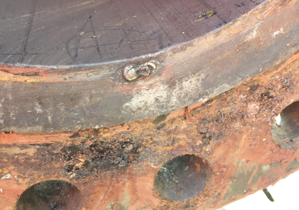
Figure 1. Bolted flange failure due to an AC fault on an unprotected joint
The high energy from the fault not only burned through the isolating gasket, but also literally welded the two flange faces together. Since the isolation joint was shorted, the CP system was compromised, and the affected pipeline was left without adequate protection until the short was identified and remedied. In this case, the entire bolted flange connection had to be replaced at considerable expense.
Due to the obvious safety risks, especially in hazardous locations and to the potential for costly pipeline damage, it is important that isolation joints be protected by controlling the differential voltage across the joint to be well below the isolator’s withstand voltage during lightning and AC fault events.
Common Solutions for Isolation Joint Protection
When properly protected, excess voltage across the isolation joint is limited by providing an alternate, lower impedance path for current to flow around the joint during over-voltage conditions. Of course, to maintain proper isolation for cathodic protection, the protective device must not conduct direct current (DC) under normal operating conditions. Both solid-state over-voltage protection devices and isolating spark gap devices are commonly used to protect isolation joints from such over-voltage conditions. Spark gaps are relatively low cost and effective for lightning protection. However, one of the key limitations of spark gaps is that their typical ratings for AC fault current are well below the fault levels commonly observed on pipelines.
What Happens When AC Faults Reach a Spark Gap?
As a rough approximation, AC fault currents of 3-10 kArms or greater can be expected to flow through an isolation joint protective device on pipelines located near HVAC lines. For specific applications, numerical modeling tools should be used to provide precise predictions of fault current along the pipeline and the appropriate ratings required for the protective devices.
Any device used on isolation joints for over-voltage protection should be properly rated to safely operate following exposure to such AC fault levels. If the device is under-designed for AC fault current, it will eventually fail either in a closed state – in which the device becomes a permanent short circuit and defeats the purpose of the isolator, or in an open state – in which the device no longer conducts current for AC faults or lightning and so is unable to provide proper over-voltage protection. Both failure modes are undesirable, but failure in an open state is particularly problematic because it presents a potential safety hazard from over-voltage and/or arcing and exposes the joint to possible permanent damage.
Spark gap devices are effective for protection against lightning and low-level fault currents. However, the total energy from an AC fault is orders of magnitudes greater than that from a typical lightning event, for which spark gaps are primarily designed. This is because an AC fault can last much longer and therefore presents much higher total energy than lightning.
Spark gaps are not designed or rated to endure the high energy level associated with common AC faults, with typical ratings of only 500 Arms for 200 ms. During conduction, the arc formed between the internal gapped electrodes can degrade the electrodes and, over time, result in either a failed-open or failed-shorted device. When the device fails open, in some cases the electrodes burn back, increasing the air gap separating the electrodes and thus increasing the spark-over voltage required for conduction upon successive faults or lightning events. In other fail-open scenarios, the terminal components break apart or the entire assembly simply falls apart. In either case the result is a permanent failed-open condition. When the device fails shorted, the high energy dissipation simply over-heats and deforms the internal components such that a permanent short is formed.
Figures 2-5 illustrate an example of a spark gap that has failed open during fault current testing. Figure 2 shows an oscillograph of a new spark gap under an initial fault current test at 2500 Arms / 745 Vrms at 60 Hz for 200 ms. Note that once the voltage across the unit (blue trace) exceeds the spark-over voltage (-784 V in this test), the device goes into conduction and passes current (red trace).
Successive tests were performed on this sample, with time between tests to allow for cooling. Upon the sixth test at 2500 Arms, the device had failed open as shown in the oscillograph of Figure 3. Note that though the voltage (blue trace) across the device is at 1043Vpk, well over the spark-over voltage, no current (red trace) passes through the unit.
Figure 4 shows the internals of this failed spark gap test sample. The internals of a similar sample prior to testing are shown in Figure 5. Note in Figure 4 how the electrode appears to have lost material which increased the gap size.
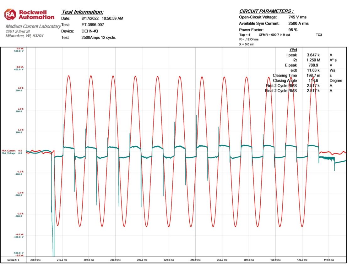
Figure 2. Oscillograph of a new spark gap under initial fault test at 2500 Arms / 745 Vrms / 200 ms
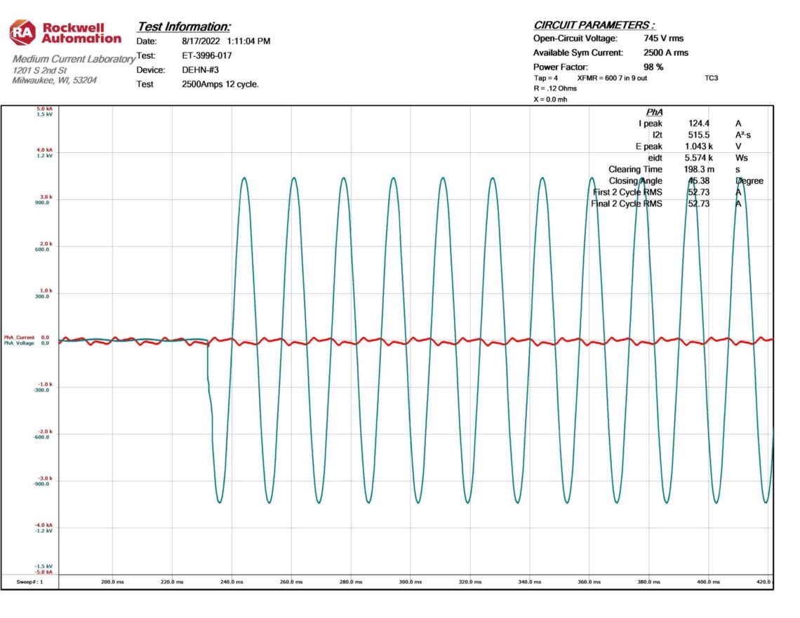
Figure 3. Oscillograph of a spark gap under subsequent fault test at 2500 Arms / 745 Vrms / 200 ms. The sample failed open.
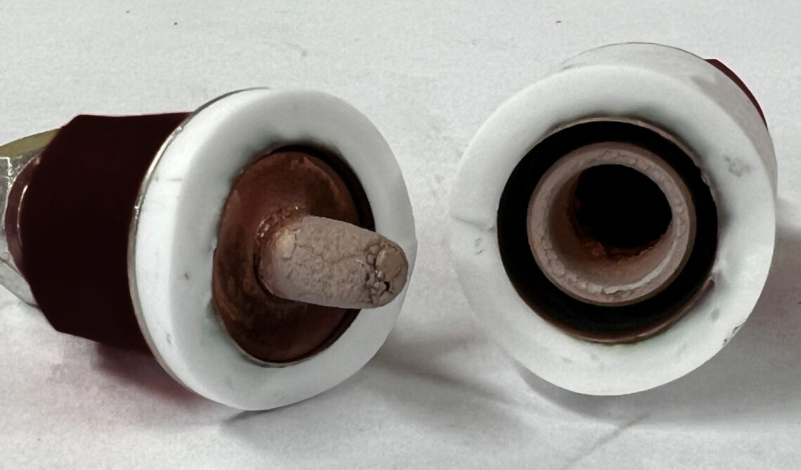
Figure 4. Internals of spark gap following tests at 2500Arms. The sample failed open.
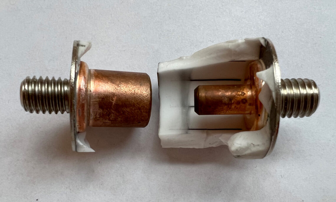
Figure 5. Internals of the spark gap prior to testing
To be fair, this unit was tested far above its published AC current rating. However, the failure mode observed reveals inherent weaknesses associated with the basic technology of a spark gap when exposed to fault current levels common to pipelines. Like this tested sample, spark gaps can often fail in an open state, leaving the isolation joint, storage tank, or wherever it is applied, exposed to potential arcing until it is replaced. And by failing open, this dangerous condition is not easily detected in the field using a basic resistance check.
Dairyland Devices are Built to Handle AC Faults
Unlike spark gaps, Dairyland decouplers and over-voltage protectors are designed and built to ensure isolation joints and pipelines are protected from high energy AC faults common to pipelines. Popular Dairyland devices are rated and certified to 3.7kArms at 0.6 s and are available with ratings up to 15kArms at 0.6 s. Dairyland devices also protect personnel from over-voltage conditions and have clamping voltages far below that of spark gaps. Unlike spark gap devices, Dairyland solid state devices have shown to be so highly reliable that they have no need for periodic testing or replacement, equating to lower operating and maintenance costs.
Want To Dive Deeper?
Join One of Our Learning Events.
Our event schedule provides you the in-depth product and application training you need to correctly apply Dairyland products.