Technical Article
Don’t Take Chances with Grounding Mat Design – Protect Your Workers!
Pipeline designers frequently specify grounding mats to protect workers from step and touch voltages caused by AC induction. But often, they assume that the grounding mat also adequately protects them from over-voltage conditions caused by lightning strikes. This can be a fatal mistake.
It is important to remember that induced AC current is much different than current caused by a lightning strike. Not only is the magnitude of lightning current much greater than that of induced AC, but the frequency content of lighting is also much higher, and this results in dramatic differences in the way grounding systems respond to each type of disturbance. A ground mat design may be adequate to address the voltage drop created by induced AC current but be completely insufficient in limiting the over-voltage conditions created by a lightning strike. For this reason, it is important to take both events into consideration when specifying a grounding mat to ensure worker safety.
The basics of gradient control mats
The purpose of a gradient control mat is to limit step and touch potentials to safe levels for workers. Step potential is the voltage between a worker’s feet when standing on the soil surface. It is based on a 1-meter separation between the worker’s feet, as specified by the NACE SP0177 standard. Touch potential is the voltage between two points with which a worker can come in contact. This is based on a worker reach of 1-meter, according to NACE SP0177. Typically, it is the voltage difference between where someone can touch the pipe and where their feet touch the ground.
Gradient control mats are typically installed under a few inches of high resistivity washed stone in areas near pipelines where personnel may walk and come in contact with above-ground portions of the pipeline. The mat is electrically bonded to the pipe to minimize touch potentials.
Three popular types of grounding mat designs are spiral wire, zig-zag and welded grid.
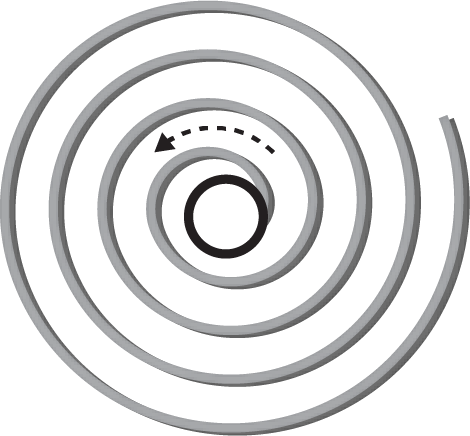
A spiral mat looks just like its name implies. Seen from above, a spiral of single-conductor ribbon or wire surrounds a pipeline segment coming out of the ground with the wire bonded to the pipe on one end.
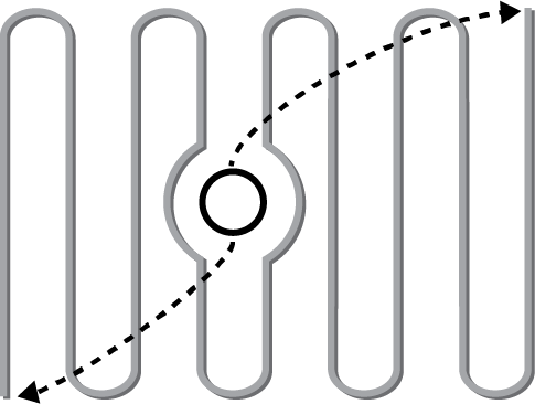
Similarly, a zig-zag mat is a single conductor laid out across the area surrounding the pipe with the wire typically bonded to the pipe at both ends.
 |
 |
 |
| Spiral Wire Mat | Zig-Zag Mat | Grid Mat |
In a grid-type mat, a closely spaced wire grid (Dairyland’s GCM uses 3 inch grid spacing) surrounds the appurtenance and nearby areas with one or more bonds between the mat and the pipe.
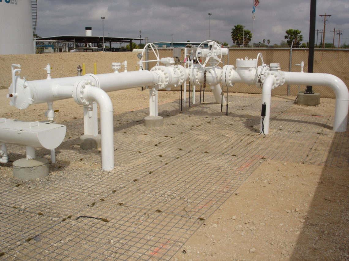
Dairyland Grid Type Gradient Control Mat installed in a station (before being covered with washed stone)
What type of grounding mat design is best?
Most mat designs work reasonably well for controlling touch and step potentials for power frequency disturbances such as AC faults and induced AC. However, lightning is much more difficult to control due to its high frequency content. Lightning can create several thousands of volts across even short sections of wire. See our article, Conductor Length Effects Upon Over-Voltage Protection From Lightning Conditions for a more detailed discussion of voltage drop across conductors due to lightning.
Applied to single conductor spiral or zig-zag grounding mats, lightning can result in extremely high touch and step potentials due to the high inductance associated with the longer conductors used in these types of mats.
In contrast, a grid-type mat provides minimal conductor distance between points of contact for personnel. Therefore, the inductance and the resulting differential voltage exposure during a lightning event, is minimized.
To illustrate this effect, a CDEGS* analysis was performed on 8 ft x 8 ft mat sections having different designs: The Dairyland grid type Gradient Control Mat (GCM), a spiral mat and a zig-zag mat. A simulated lightning surge current of 30kA with 1×50µs waveform was injected 50 feet from the mats in soil with uniform resistivity of 50 W-m. The figure below shows the difference in performance of each mat type in terms of body current over the duration of the surge event. The black curve represents the body current limit for ventricular fibrillation per IEC 60479-2.
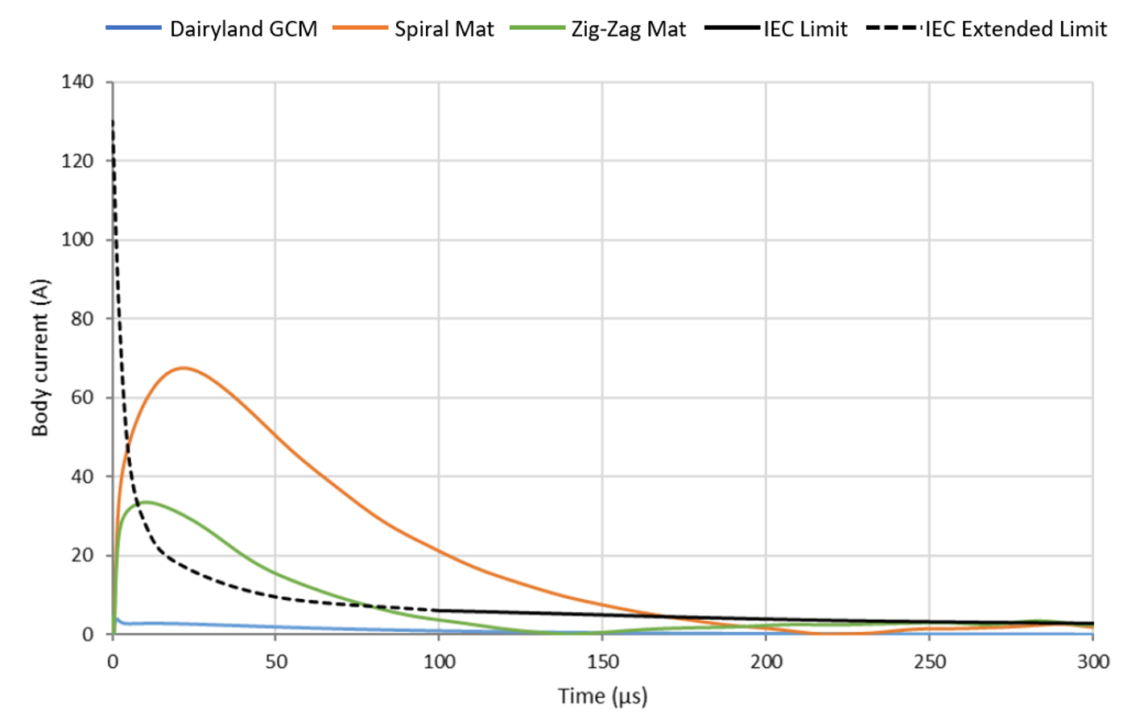
Body Current for 50 Ω-m soil – 15 m from current injection
Note that the Dairyland grid type GCM provides by far the best overall protection. This is just one simulated scenario. But the trend of relative performance between mat types is clear.
How the decoupler fits in
Regardless of which design is used, a decoupler should be placed in series between the pipeline and the ground mat to prevent any loss of cathodic protection current to the mat. The decoupler will block CP current (DC) while simultaneously bonding the pipeline and grounding mat for AC continuity. With the decoupler in place, the grounding mat material has no effect upon the pipeline’s CP.
Since Dairyland decouplers are independently certified by UL to be a fail-safe electrical bond under the rated AC faults and lightning conditions, you can be confident that the pipe-to-mat bond will remain intact wherever Dairyland decouplers are installed.
Conclusion
Where your workers can be exposed to electrocution hazards, don’t take chances with grounding mat design. Be sure to design and install appropriate grounding mats to provide adequate protection for personnel, both for step and touch potentials.
Regardless of the style of grounding mat used, a decoupler is an important addition to isolate the grounding mat from the pipeline – to ensure cathodic protection while providing safety bonding and grounding.
* CDEGS software developed by Safe Engineering Services & Technologies. The analysis was performed by Corrosion Service Company Ltd.
Want To Dive Deeper?
Join One of Our Learning Events.
Our event schedule provides you the in-depth product and application training you need to correctly apply Dairyland products.