A New Solution for Efficient, Accurate, and Safe Interrupted Surveys
Electrical potential surveys are often required on cathodically protected structures such as underground pipelines. However, proving that a cathodic protection system is providing the degree of corrosion protection expected can often be a time-consuming and error prone endeavor. It is usual to interrupt the CP source to carry out these surveys, the accuracy of which is affected by several factors, including the presence and design of DC decouplers.
This article discusses how and why traditional decouplers can affect interrupted survey measurements and instant-off data, and reviews some existing solutions to these issues. A new decoupler solution for ensuring the accuracy, efficiency and safety of interrupted surveys will be introduced.
Interrupted Surveys and Decouplers
Watch Your Waveforms
The purpose of potential surveys is to evaluate the effectiveness of the cathodic protection (CP) system by measuring the polarized potential of the pipeline. However, pipe-to-soil potential measurements are influenced by the CP current, which introduces a measurement error known as IR drop. To eliminate this error, CP sources are synchronously interrupted momentarily, after which the potentials are measured, but before the pipe depolarizes. The potentials measured in this way are referred to as instant-off potentials. Such interrupted measurements are typically collected over the length of the pipeline as part of a Close-Interval Survey (CIS) or Close- Interval Potential Survey (CIPS). A typical instant-off potential response is shown in Figure 1.
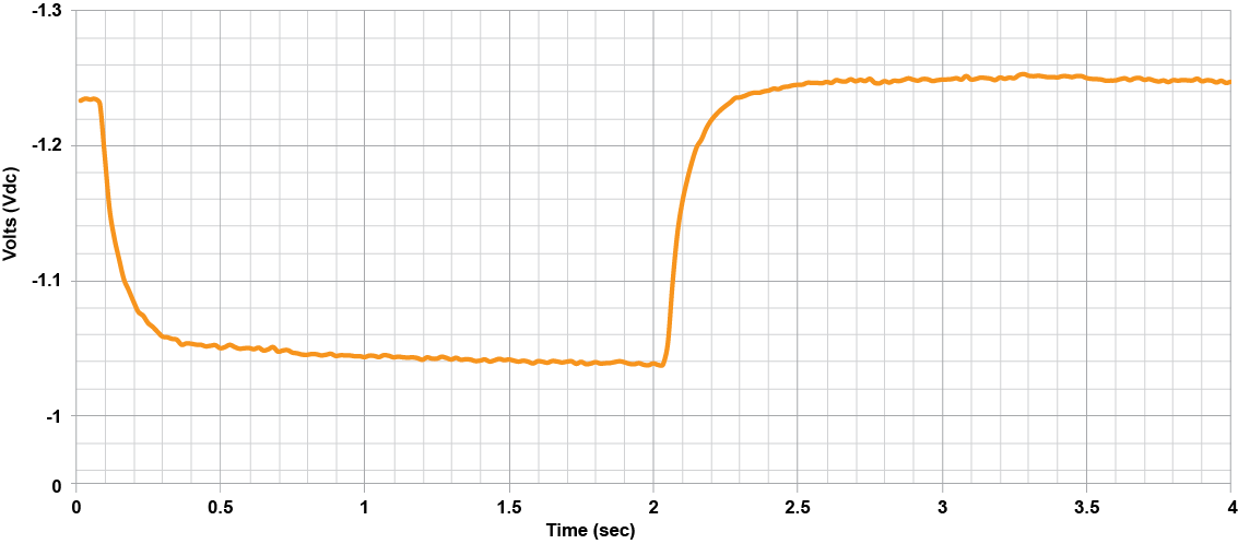
Figure 1 – A typical instant-off response measured on a pipeline.
Ideally, instant-off measurements are taken within 300-400 milli-seconds (ms) after interruption. This is usually a long enough time to avoid any spiking that may occur following the interruption, yet short enough to minimize depolarization of the pipeline and to minimize the duration of the OFF cycle, and thus the total time required to conduct the survey.
However, the interrupted response of pipeline systems can vary greatly depending on system parameters such as soil resistivity, length and diameter of the pipeline, pipeline coating, coating holidays and the number of decouplers present. Certain combinations of these parameters can significantly change the response and, if not accounted for, can lead to instant-off readings that are more electro-negative than the true polarized potential. Therefore, before recording instant-off measurements, CP Technicians should evaluate the interrupted response to determine the appropriate ON-OFF cycle durations and instant-off measurement times, as well as to account for any interference issues.
The Decoupler Dilemma
DC decouplers play a critical role in most CP systems by providing effective DC isolation of cathodically protected structures from other objects and earthing systems, while simultaneously bonding the structure to earth for AC (induced steady state and faults) and lightning. Commonly employed in AC mitigation systems, decouplers utilize a capacitor to provide a continuous conduction path for steady state induced AC current to pass to ground. The capacitor must be large enough to present a suitably low impedance to the induced AC and so minimize the AC voltage on the pipeline. However, this capacitance can have a detrimental effect on the instant-off response of interrupted surveys. This effect can be observed by comparing the waveforms shown in Figure 2.
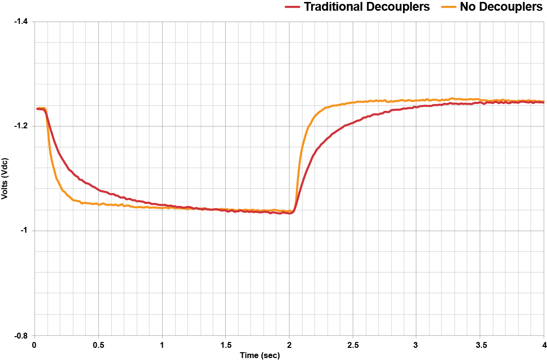
Figure 2. Instant-Off Response with and without a traditional decoupler
In this example, there were eight decouplers installed on a segment of pipeline approximately 53 km long. Note that the change in the response due to the addition of the decouplers can introduce a significant error in the instant-off measurement, depending on when it is sampled.
Knowing this phenomenon, several questions arise: At what point in the OFF cycle should the instant-off data be sampled? How late in the OFF cycle can an instant-off measurement be taken with confidence that the pipe has not depolarized? How consistent is this effect over the length of the pipeline? These are questions that have plagued CP technicians for years.
Why decouplers affect the interrupted response – a simple electrical model
Much as the ride of a car depends not only on the spring rate of the suspension, but also on the shock absorbers and the mass of the vehicle, the instant-off response on a pipeline is influenced by decoupler capacitance in combination with other physical parameters in the pipeline/ICCP/decoupler system, predominantly pipeline coating and soil resistivity.
To better understand how these parameters influence the interrupted response, it would be helpful to analyze the pipeline/ICCP/decoupler system using a simple electrical circuit as shown in Figure 3.

Figure 3. Simple Electrical Model of a Pipeline, ICCP System and Traditional Decouplers
In this model, the pipeline is represented by the longitudinal resistance, RL, and inductance, LL, together with the coating resistance, RS, in parallel with the capacitance of the pipe/soil interface, CS. The voltage that is developed at the pipe/soil interface due to polarization is denoted by ES. Further, the pipe metal exhibits a DC corrosion potential with respect to the soil EP, which typically has a magnitude of approximately -0.6VCSE. Finally, there is a resistance, RP, between the outer surface of the pipeline coating and remote earth. The CP system rectifier and interrupting switch are denoted by VR and S1 respectively. When the pipeline is protected by the CP system, S1 is closed allowing DC current, ICP, to be supplied to the pipeline via an anode bed with resistance RA.
When decouplers are installed, an additional capacitance (CD) is added to the system, along with the associated voltage across the decoupler (ED). The decoupler earthing system has a corrosion potential denoted as EG and a resistance to remote earth, RG.
With CP current applied, once the decoupler capacitor has fully charged, the DC current through the decoupler falls to zero and, following Kirchoff’s law, the voltage equilibrium in this circuit can be represented by the following equation:
ES + EP + ICP x RP = ED + EG
When the CP current is interrupted, ICP drops to zero and, since corrosion potentials EP and EG remain constant, the voltages ES and ED respond to compensate for the change in ICP (i.e., the pipe begins to depolarize and the decoupler capacitor dissipates stored charge). This results in a transient flow of current from the decoupler that essentially acts as an uninterrupted source and will introduce error in instant-off measurements until the charge across the capacitor is fully dissipated.
Although the actual system is much more complex, in general, the interrupted response of this system can be characterized by that of an RC (Resistors + Capacitors) circuit. The step response of an RC circuit has exponential decay for which the rate of decay over time is inversely proportional to the product of the circuit resistance and capacitance, commonly referred to as the RC time constant. In a pipeline circuit, the larger the RC time constant is, the longer it will take for the decoupler charge to dissipate after interruption, and the greater will be the challenge to collect accurate instant-off measurements in a timely manner.
In a typical cathodically protected pipeline, the resistance portion of the RC time constant is influenced by both the pipeline’s resistance to remote earth, RP, and the pipeline’s coating resistance, RS. Soil resistivity near the pipeline is the major contributor to Rp and the overall circuit resistance. As improvements in pipeline coatings have been made over the years, the RS portion of the total circuit resistance has increased. But RS tends to reduce with greater pipeline surface area (i.e., larger pipe diameter and longer pipeline segment) since the number of possible holidays typically increases with surface area. The decoupler earthing system resistance, RG, is typically low by design and so usually does not significantly influence the RC time constant. The circuit capacitance is controlled mostly by the decoupler capacitance.
Given these relative parametric influences on the pipeline/ICCP/ decoupler system, combinations of the following trends can result in greater system RC time constants and thus increased likelihood of experiencing challenges with collecting accurate instant-off measurements within 300-400 ms after interruption.
- A higher density of traditional decouplers (number of decouplers per length of pipeline)
- Higher soil resistivity
- Higher resistance pipeline coating
- Smaller diameter pipeline
- Shorter pipeline segment
Traditional solutions
How can accurate and timely interrupted surveys be conducted if decouplers are part of the system?
Historically, there have been methods to deal with the effects described above. However, as will be explained, each of these traditional solutions has significant shortcomings.
Disconnecting Decouplers
One common solution is to temporarily disconnect the decouplers from the pipeline during the survey. This is effective in eliminating the transient current flow during the OFF cycle and the resulting IR drop, as the decoupler capacitance has been removed from the system. This can be accomplished by physically disconnecting leads or by the installation and use of decoupler isolation switches. However, there are several reasons why this option should be evaluated carefully. First and foremost, while the decouplers, and thus the AC mitigation system, are disconnected, the pipeline is not protected from induced AC, AC faults or lightning and unsafe voltages may be present on the pipeline. This presents a safety hazard to those conducting the interrupted survey or anyone else in contact with the pipeline or its appurtenances. In addition, while the decouplers are disconnected, the pipeline may be exposed to the damaging effects of AC corrosion. Another drawback of this approach is the significant amount of time required to disconnect and reconnect all decouplers in the pipeline circuit being studied, compounding the time and cost needed to perform an interrupted survey.
Extending the OFF Cycle
Another method of conducting accurate and timely interrupted surveys is to extend the OFF cycle of the rectifier to ensure the response has stabilized. Sample waveforms should be evaluated at several locations along the pipeline to determine the optimum ON-OFF cycle time required. The obvious drawback to this approach is that it could make for a much slower and more expensive survey. Some applications have been observed which would require OFF cycles on the order of 10 seconds for the capacitor charge to sufficiently dissipate.
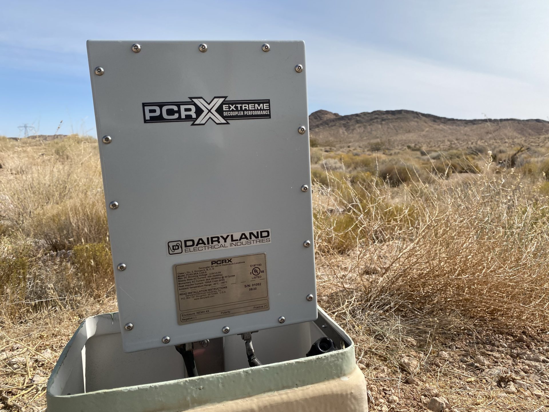
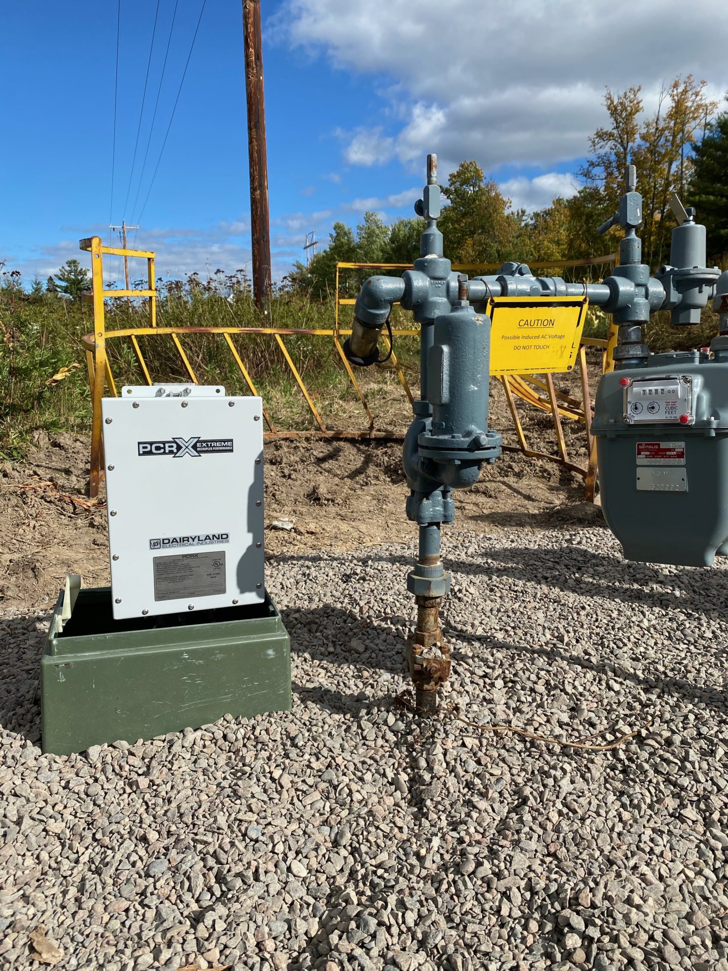
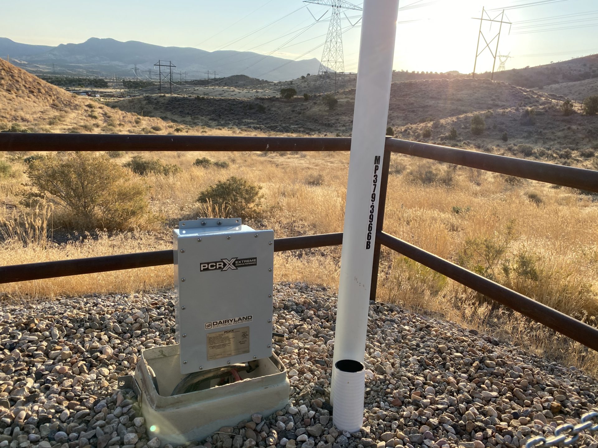
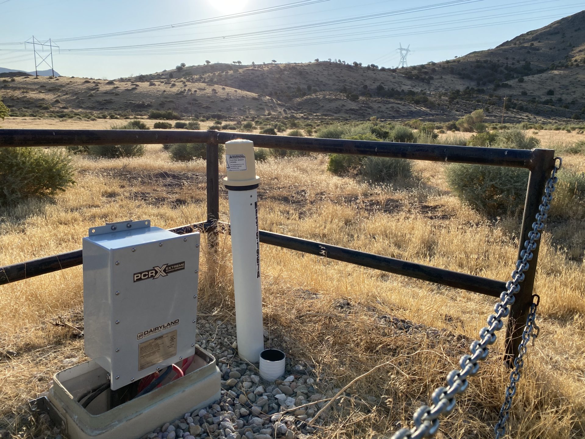
Figure 4. AC Mitigation With Next Generation PCRX Decoupler
A New Solution – Decoupler “Camouflage”
A new decoupler technology is now available that can overcome the slow interrupted response associated with the capacitance in traditional decouplers, while providing all the same benefits of traditional solid-state decouplers. The PCRX remains in the circuit at all times during an interrupted survey to provide continuous protection from AC interference, yet virtually eliminates the effect of capacitance common to traditional decouplers. This new decoupler technology uses sophisticated and proprietary signal handling that results in interrupted responses similar to that of having no decouplers present in the circuit. PCRX devices provide the same DC isolation performance as traditional designs and are available with standard ratings similar to those of traditional decouplers.
Field Test Results
The PCRX has been tested on several pipeline AC mitigation installations over a wide variety of system conditions, such as soil resistivity, pipeline diameter and length of pipeline segment, decoupler density, and isolated and non-isolated pipeline segments. Since several factors other than decoupler capacitance can influence the interrupted response, the performance of the decouplers was measured by comparing interrupted response waveforms with and without the decouplers installed.
A sample waveform from an interrupted survey conducted on a pipeline located in the western United States is shown in Figure 5. The pipe was 24 inches in diameter and electrically continuous for approximately 53 km and coated with a fusion bonded epoxy (FBE). There were eight decoupler installation sites along the length of this pipeline segment and the soil conditions were sandy and dry. Each of the waveforms shown were taken within the same day.
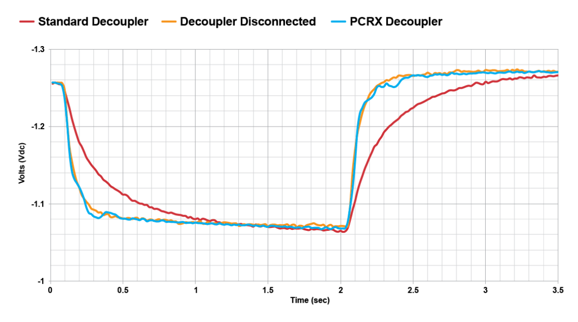
Figure 5. Interrupted Response Waveforms. Test Location CK-810.
Note that the response with PCRX devices installed closely mimics the response with the decouplers disconnected. The measurement error associated with decoupler capacitance is eliminated.
Figure 6 shows another set of waveforms taken on a different pipeline in the midwestern United States. This lateral pipeline segment was 3.2 km long and a mix of 6 in and 8 in diameter piping, all with FBE coating. There were eight decoupler sites along this segment. However, this pipeline segment was not isolated from the main pipeline, on which additional decouplers were installed. The soil was moist farm topsoil.
Comparing these waveforms with those of Figure 5, it is interesting to note the extremely slow response of each waveform, especially that with the traditional decouplers installed (Note that the OFF cycle was cut short for the test with traditional decouplers, but the trend is still apparent.). The lower soil resistivity in the later example would lead one to expect a smaller RC time constant and thus a faster decay of the interrupted response. However, in this installation, the density of traditional decouplers averages 16 times that of Figure 5 and this difference in decoupler capacitance overwhelms the difference in soil conditions between the two applications.
It is also notable that even the interrupted response with the decouplers disconnected is extremely slow and would result in erroneous instant-off measurements roughly 70 mV too electronegative if taken within 0.5s of interruption. This slow response is due to the tested pipeline segment not being isolated from the main pipeline where other decouplers are installed and highlights the need, at least in this case, to apply PCRX devices at all decoupler sites.
As in the previous example, the response with the PCRX installed again aligns with the response with the decouplers disconnected. This behavior was similar across all testing performed using these new decouplers, validating the performance of this new camouflage technology.
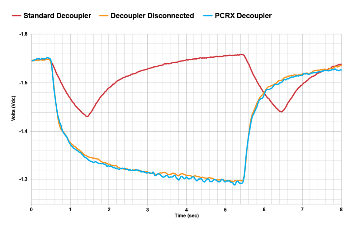
Figure 6. Interrupted Response Waveforms. Test Location WO-08.
The Benefits of “Camouflage” Decoupler Technology
More Accurate Potential Surveys
When properly installed on isolated pipelines, the PCRX can virtually eliminate the measurement error associated with decoupler capacitance. Due to the capacitive effects of traditional decouplers, unless considerable attention is given to waveforms and the proper timing of instant-off measurements throughout a survey, there is significant chance of recording overly electronegative OFF potentials and thus potentially not identifying an insufficiently protected pipeline.
Safer Surveys
With the PCRX in place, there is no need to disconnect the decouplers during a survey. Induced AC current, as well as potential AC faults and lightning, passes to ground and the AC voltage on the pipeline remains at safe levels throughout the survey. This also ensures that the measures for mitigating AC corrosion remain in place during the survey.
Faster/Lower Cost Surveys
Finally, the time and cost to conduct the survey are likely reduced from that using traditional solutions. The additional time required to either disconnect/reconnect decouplers or to extend OFF cycles sufficiently to collect a valid measurement can add many hours and significant cost to a typical survey. The PCRX eliminates this added time and the associated recurring costs.
Summary
Interrupted surveys on cathodically protected structures are subject to many variables that influence the accuracy, time, and cost of the survey. Often used for AC mitigation, DC blocking and safety grounding, traditional DC decouplers can have a notable effect on the potentials measured during an interrupted survey which can result in inaccurate conclusions about the protected state of the structure. A few key CP system circuit parameters, including the capacitance of traditional decouplers, have significant influence on the interrupted response. When these factors result in excessively long decoupler dissipation times during the OFF cycle, it is likely to either cause measurement error or require considerable effort to mitigate.
This article described the new decoupler technology found in the PCRX, which allows for more accurate and efficient interrupted surveys while maintaining the safety benefits for which decouplers are intended. The PCRX virtually ‘camouflages’ itself following interruption and results in interrupted responses and instant-off measurements nearly identical to those measured with no decouplers installed. The technology has shown to be effective over a wide range of field conditions.
A version of this article originally appeared in the July/August 2021 issue of Corrosion Management the magazine if the Institute of Corrosion.
Want To Dive Deeper?
Join One of Our Learning Events.
Our event schedule provides you the in-depth product and application training you need to correctly apply Dairyland products.