Misconceptions of Over-Voltage Protection
Always Rugged. Always Reliable. — This is Dairyland’s promise when it comes to product design. With almost 40 years of experience, we create a safer world through highly engineered products as well as by sharing our expertise. Throughout our decades of client interactions, we’ve noticed some common industry misconceptions relating to over-voltage protection. Below, we examine a few of the most common.
AC Corrosion vs. Personnel Safety
Our first misconception is that AC voltage mitigation for safety will address AC corrosion. Although an exceptional mitigation system could potentially do so, AC corrosion is the result of specific current densities. Let’s look at the following chart:
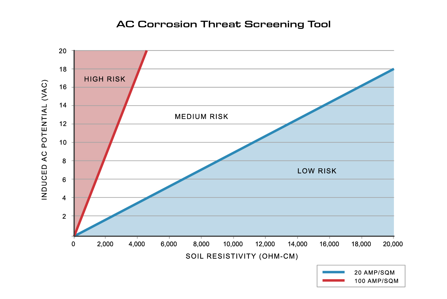
Figure 1: AC Corrosion Threat Screening Tool (Induced AC)
You can see that depending on your soil resistivity, even low levels of induced AC can create high-risk areas where AC corrosion can occur. It’s important to mitigate AC voltage with both personnel safety and AC corrosion in mind. If AC corrosion is a concern, work with your modeling design firm to make sure your mitigation plans account for both personnel safety and AC corrosion risk.
On that note, let’s talk about personnel safety and the industry standards addressing it. NACE SP0177, the corrosion industry’s guideline to managing voltage, suggests keeping your structure under 15 Volts-AC. The reasoning behind such a value relates to the average human body’s resistance of 1,000 Ohms and “let-go” current of 15mA.
Utilizing Ohm’s law, we get roughly 15 Volts-AC as our guideline. However, every human is different and much lower values could still be unsafe. All of us want a safe working environment, so we suggest you always work for the lowest AC voltage on your pipeline. And as proven above, the personnel safety standards don’t account for other phenomena.
Conductors: Inductance and Length
Our next misconception relates to conductors and the effects that current has flowing through them. I’m sure we’ve all heard of an “inductor” before – but do we understand the principle of this inductance effect?
Inductance is when an electrical conductor opposes the change in current flowing through it. This is very important to understand as we address situations like lightning. During these events, we see a spike of current which a conductor will resist. Like water pressure building in a hose, our conductor will create a large voltage drop across its length.
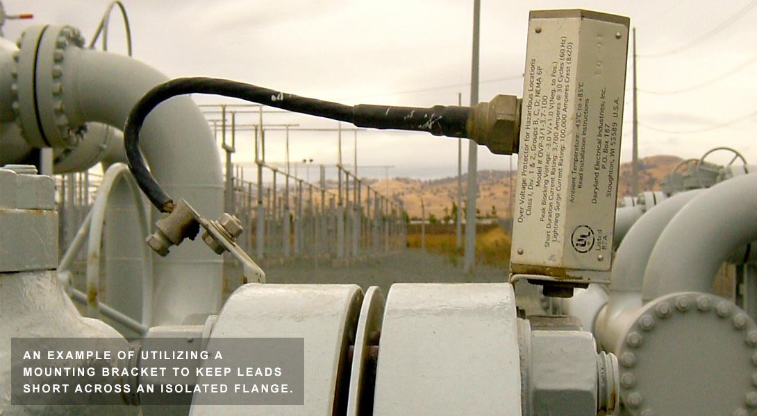
If you’ve ever used a Dairyland product to protect an isolated flange (like an OVP), you should now understand why we suggest keeping the leads short. What would happen if we used multiple feet of conductor to connect across the flange? Due to the inductance effect under lightning, that conductor will resist the flow of current, creating a voltage drop large enough to potentially damage the conductor coating and create arcing, which may result in the isolation flange not being protected. This would undermine the entire installation and cause damage to equipment. Click here for more information.
Conductors: Waveforms and Ampacity
Let’s address the next misconception while we’re still on the topic of wires: conductor length isn’t the problem in every application. As previously discussed, large electrical pulses like lightning (which behave differently than AC or DC waveforms) will bring about this inductance effect, creating concerns with conductor length. In AC fault scenarios, it’s not the conductor length that matters, but rather the ampacity rating of the wire itself. AC faults create a different waveform than lightning and are greater in duration, which means that the conductor must be able to handle the fault current for an extended period. Selecting the right conductor for each application is critical to ensure a safe, reliable installation. Click here to read more on this topic.
Total Electrical Isolation: The Truth
Now we’ll address our last misconception for this article. In the world of cathodic protection, we are forever plagued by the job of maintaining adequate protection levels. Mitigation systems, station grounds, electrical equipment grounds, and more, will always be a pathway to losing CP. It can be very tempting to want total isolation in these situations, however, that would be incredibly dangerous and could be outside electric code. Total isolation from ground on any structure or equipment would allow voltages to rise to very unsafe levels. That’s why we manufacture devices that simultaneously provide DC isolation and AC continuity: to ensure that CP levels are maintained, but each structure is safely referenced to one another.
This discussion is testament to the complexity of the Cathodic Protection industry. From understanding waveforms to personnel safety, there’s much to learn and remember. We hope this article has been beneficial to our readers and will continue to prompt best practices in the field.
For more information, please visit our website at www.Dairyland.com.
Want To Dive Deeper?
Join One of Our Learning Events.
Our event schedule provides you the in-depth product and application training you need to correctly apply Dairyland products.